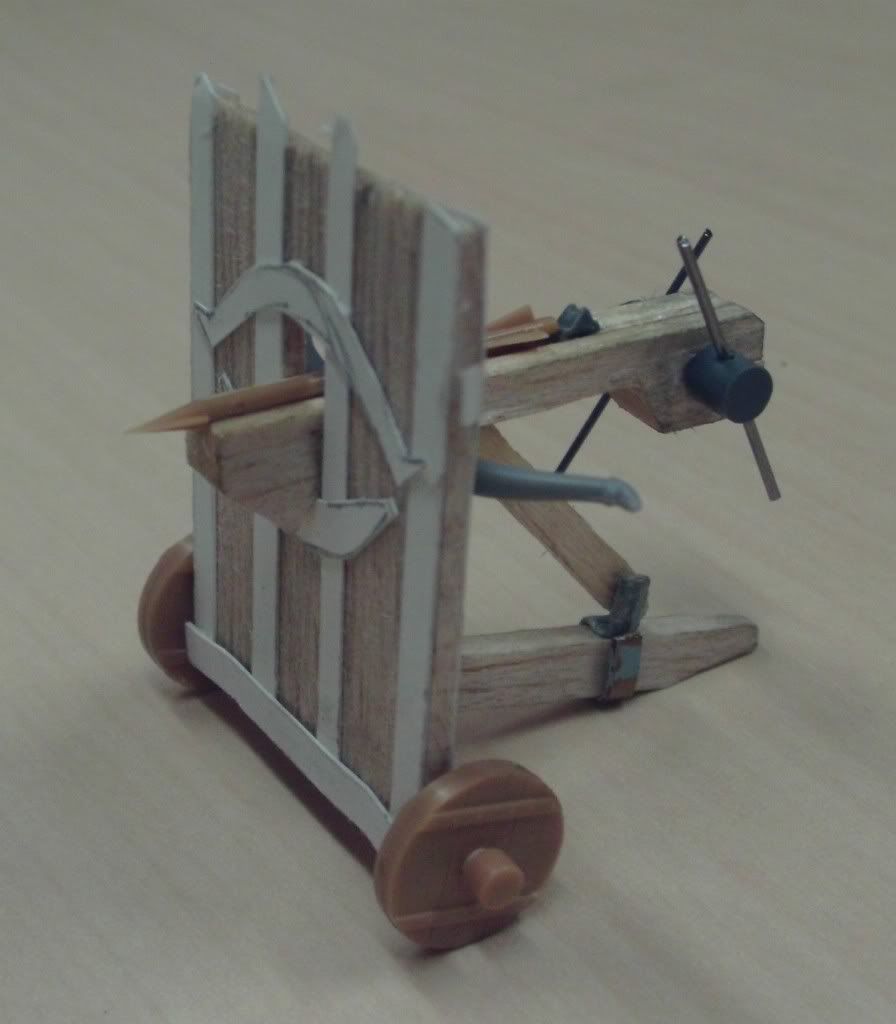
I thought I'd share my prototype ballista design which I intended for use with my 28mm LotR figures. What started off life as a means to use up the extra bits from the Zvezda siege engines kit rapidly grew into a more ambitious project. I liked the look of the 'mantlet' style mini by GW but I noticed several design features that made their kit less than portable. The addition of wheels under the mantlet seemed a fundamental improvement to the design, as was a simplified support and aiming structure for the weapon. I took my design cues from Chinese and Classical ballista designs to arrive at the current marque. I wanted to achieve a robust and simple yet efficient looking design without any fancy embellishment. This is after all a functional war machine made by a culture not noted for its artistic excellence.
The first step was to model a mantlet using flat balsa with card strips to simulate the metal reinforces. To this I will add the heads of railway track pins as nail/bolt heads into predrilled holes.
The next stage was to add a 5mm thick beam at the base to be the main axle for the wheels. This was glued in place with a central notch cut for the trailing T bar support strut. A hole was predrilled to take a track pin which will act as a central securing bolt for the T bar. The underside of the T bar was beveled and may ultimately have a 'metal' skid or shoe added out of card.
Suitable reinforcing card strapwork was applied to the mantlet and wrapped around the ends of the axle. Holes for the axles were drilled and Zvezda mantlet wheels glued in place using stub axles of brass rod.
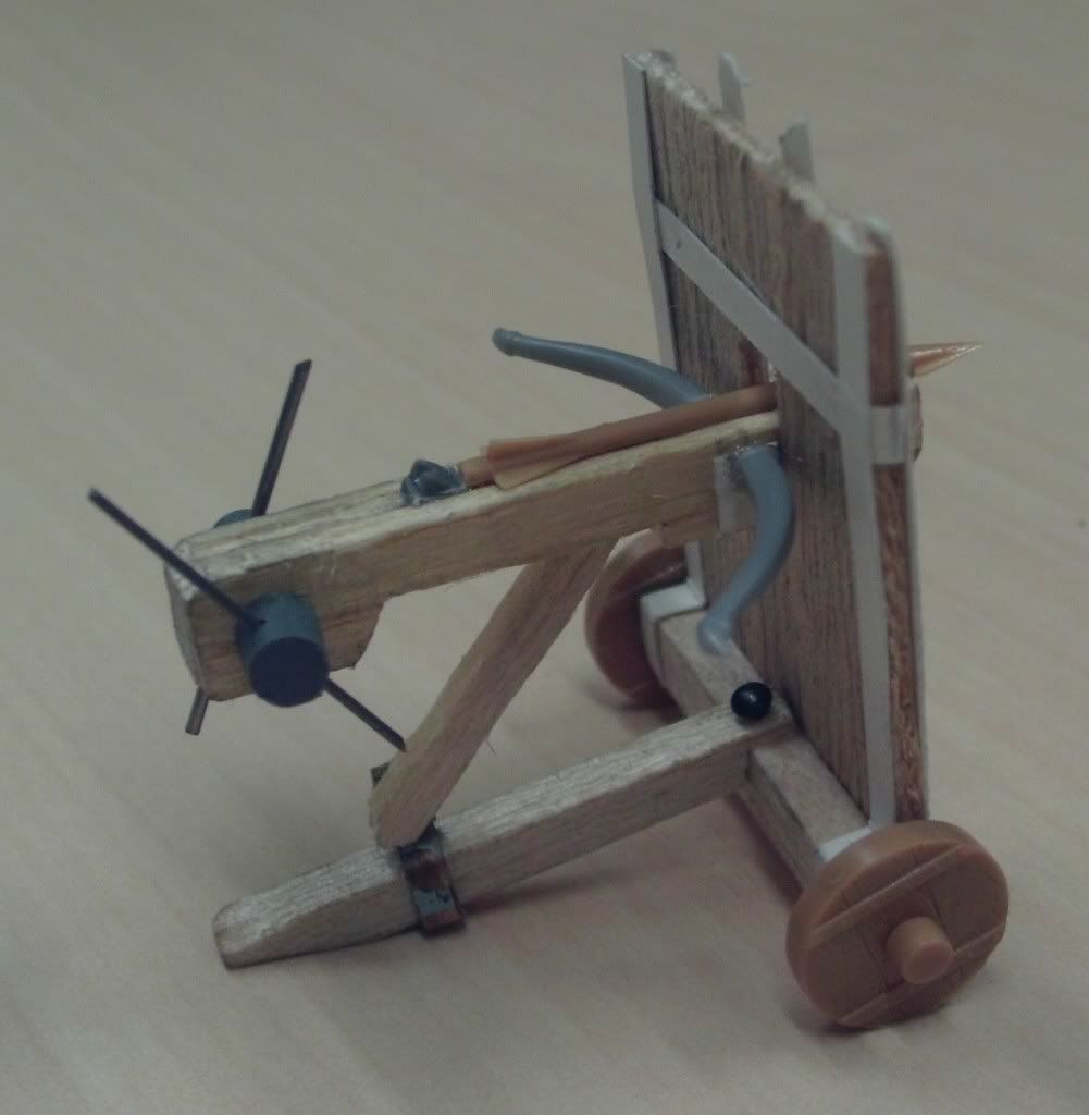
A thick beam of balsa/obeche wood ws used as a suitable tiller for the crossbow, with a stepped front which hooked over the slot in the mantlet. A cut out (to reduce the weight and to take the vertical support strut) was modelled on the underside. The rear of the stock was rounded as in several Chinese examples. A longitudinal groove was carefully scribed using a blunt pencil and scalpel. The Zvezda ballista bolt was then glued in place.
Behind this a trigger mechanism was made out of a piece of scrap plastic - in this case the spiked collar from a GW lizardman spear. The spike was notched to create the double trigger and the underside shaped to fit into the groove of the slide.
The site of the bow staves was 'reinforced' using a U shaped panel of card to which the GW bow staves were glued. A leaf spring of card strips or other design could equally be used. Fuse or florists wire will be used as a bow string. I may model reinforcing rope bindings around the junction as seen on several historical examples.
The winding gear was made up from cylindrical scraps of plastic sprue with holes drilled for the levers and stub axle. The whole assembly was then glued in place.
The vertical support strut was glued in place against a strip of thin brass carefully folded around the T bar intended to suggest a hinge-like arrangement. A pin head will complete the effect. The pointed end of the strut was modelled to fit into the step, but in reality would have engaged on toothed grooves on the underside of the tiller to facilitate aiming.
Once the whole design had been set and suitable materials sourced, assembly to this stage took a little over an hour. I have sufficient materials to make a battery of three war machines.
The whole thing is designed to fit on a 50mm x 50mm base and will have suitable spent arrows and other scenic additions etc. modelled. The crew are intended to be separately based minis.


 Welcome, Guest. Please
  April 27, 2024, 02:20:26 PM